- 您现在的位置:买卖IC网 > Sheet目录394 > ANT-1356M (RF Solutions)ANTENNA RFID COIL 13.56MHZ
�� �
�
�ib� technology�
�Data� Sheet�
�ANTENNA_1356.PDF�
�6� Pages�
�Last� Revised� 18/02/08�
�Micro RWD MF (Mifare) Antenna Specification�
�The� MicroRWD� MF� (Mifare)� module� has� been� designed� to� interface� to� a� simple� high� Q�
�antenna� coil� of� around� 1uH� inductance� together� with� some� capacitor� and� resistor�
�components.� The� antenna� coil� and� passive� components� form� the� “tuned”� RLC� (Resistor-�
�Inductor-Capacitor)� circuit,� which� is� designed� to� resonate� at� the� 13.56� MHz� carrier�
�frequency� and� have� a� Q� factor� of� 35-40.� For� the� 125� kHz� family� of� MicroRWD�
�modules,� the� low� Q� antenna� (700uH)� has� a� relatively� wide� tolerance� of� inductance� so�
�the� capacitor� components� are� fixed� and� mounted� on� the� RWD� module� itself� –� pins� AN1�
�and� AN2� connect� to� an� external� antenna� coil� directly.� For� the� 13.56� MHz� MicroRWD�
�modules,� the� antenna� Q� is� higher� and� the� inductance� tolerance� is� narrow.� For� this� reason�
�the� capacitor� components� are� external� to� the� module� to� allow� fine-tuning� and� adjustment�
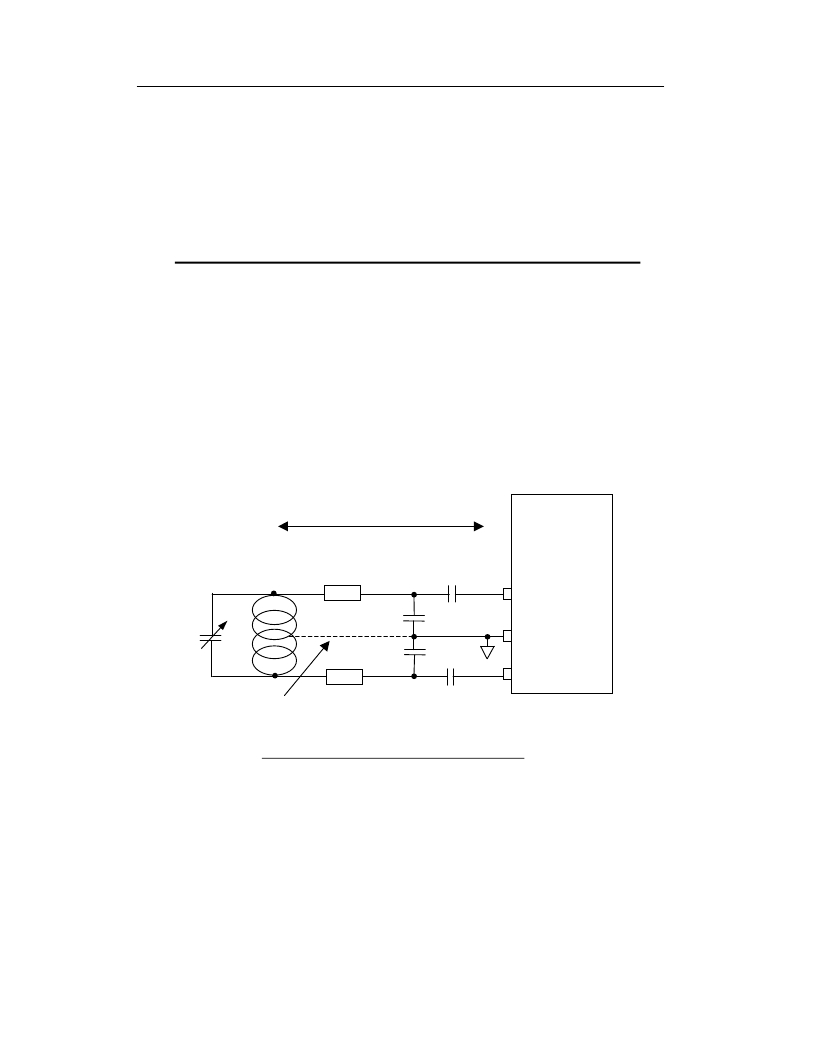
�of� the� LC� circuit� as� shown� below.� The� external� resistors� are� used� to� limit� the� antenna�
�current� and� correct� the� antenna� Q� to� 35-40� range.�
�Approx� 3cm� max�
�MicroRWD�
�65mm� diameter� coil,� 2� turns� 0.45mm� diameter�
�Enamelled� Cu� wire� (26� SWG),� approx� 1uH�
�C1� =� 22pF�
�MF�
�AN1� (pin� 9)�
�5-50pF� trimming�
�capacitor�
�Rext�
�C3� =� 220pF�
�GND� (pins� 7/13)�
�C4� =� 220pF�
�AN2� (pin� 12)�
�Centre� tap� not� required�
�for� simple� antenna�
�Rext�
�typically� <� 0.5R�
�C2� =� 22pF�
�All� capacitors� ceramic� 50v� minimum�
�NPO/COG� types� +/-� 5%� or� better�
�Directly connected antenna arrangement�
�For� maximum� range� and� performance� the� following� factors� should� be� considered:�
�1)� Maximum� range� and� coupling� between� transponder� and� RWD� is� based� on� the� ratio�
�of� their� antenna� diameters.� Very� approximately� the� RWD� antenna� loop� diameter�
�should� be� 2-3� times� the� diameter� of� the� transponder� coil.� The� basic� method� of�
�communication� is� via� magnetic� flux� linkage� (like� an� air-cored� transformer)� so� the�
�more� lines� of� flux� that� intersect� the� transponder� coil,� the� better� the� overall�
�performance.� For� ISO� card� transponders� there� is� little� benefit� in� using� an� RWD�
�antenna� larger� than� 10cm� diameter.� Circular� antenna� coils� generally� give� a� more�
�uniform� flux� distribution�
�1�
�发布紧急采购,3分钟左右您将得到回复。
相关PDF资料
AO3460
MOSFET N-CH 60V .65A SOT23-3
AO4407A
MOSFET P-CH -30V -12A 8-SOIC
AO4438
MOSFET N-CH 60V 8.2A 8-SOIC
AO4447A
MOSFET P-CH 30V 17A 8-SOIC
AO4496
MOSFET N CH 30V 10A SOIC 8
AO5803E
MOSFET 2P-CH 20V 0.6A SC89-6L
AO6808
MOSFET 2N-CH 20V 4.6A 6TSOP
AO7410
MOSFET N-CH 30V 1.7A SC70
相关代理商/技术参数
ANT14
制造商:CIT 制造商全称:CIT Relay & Switch 功能描述:CIT SWITCH
ANT1400F
制造商:RCA 功能描述:Passive Multi Directional Flat Digital Antenna - White 制造商:RCA 功能描述:INDOOR ANTENNA FLAT PANEL WHITE
ANT1400R
制造商:RCA 功能描述:Passive Multi Directional Flat Digital Antenna - White 制造商:RCA 功能描述:INDOOR ANTENNA FLAT PANEL WHITE
ANT1450BF
制造商:RCA 功能描述:RCA Low Profile Antenna UHF/DTV/HDTV Active 制造商:RCA 功能描述:RCA LOW PROFILE ANTENNA UHF/DTV/HDTV ACTIVE BLACK
ANT1450BR
制造商:RCA 功能描述:RCA Low Profile Antenna UHF/DTV/HDTV Active 制造商:RCA 功能描述:RCA LOW PROFILE ANTENNA UHF/DTV/HDTV, ACTIVE, BLACK
ANT15
制造商:CIT 制造商全称:CIT Relay & Switch 功能描述:CIT SWITCH
ANT1515B00FT1575A
功能描述:天线 1580+/-2MHz 50 Ohm PATCH ANTENNA,GPS
RoHS:否 制造商:Molex 技术类型:Cellular Antenna 频率: 带宽: 尺寸:106.7 mm L x 13 mm W
ANT1515B00FT1575S
功能描述:1.6GHz GPS Ceramic Patch RF Antenna 1.576GHz ~ 1.584GHz 1.5dBic Pin Surface Mount 制造商:yageo 系列:- 包装:托盘 零件状态:有效 频率组:UHF(1 GHz ~ 2 GHz) 频率(中心/带):1.6GHz 频率范围:1.576GHz ~ 1.584GHz 天线类型:陶瓷贴片 频带数:1 VSWR:2 回波损耗:-10dB 增益:1.5dBic 功率 - 最大值:- 特性:- 端接:引脚 侵入防护:- 安装类型:表面贴装 高度(最大值):0.177"(4.50mm) 应用:GPS 标准包装:70